|
| |
TM 5-4210-220-34
2-12.
PUMP DRIVE AND PTO - Continued
2-12.1
Power Take Off Unit - Continued
(20) Reattach mechanical puller kit to the oil supply end of the PTO housing (1). Tighten pressure screw into
oil supply end of drive shaft (30). Continue to tighten pressure screw until drive shaft is free of spider
gear assembly (24).
(21) Remove drive shaft (30) from PTO housing (1). Bearings (20 and 22) are still mounted on the drive
shaft.
(22) Carefully maneuver spider gear assembly (24) from PTO housing (1).
(23) Disassemble the spider gear assembly (24) following the procedures listed below.
(24) Remove lock ring (41). Pull clutch stop spacer (47), opposing clutch discs (39), and bronze clutch discs
(40) from the spider gear assembly (24).
(25) Compress spring (36) using arbor press. Remove lock ring (38), spring retainer (37), and spring (36).
WARNING
Death or serious injury could occur if compressed air is directed against the skin. Do not use compressed air
for cleaning or drying unless the pressure is/has been reduced to 30 psi (2.11 kg/cm2) or less. When
working with compressed air always use chip guards, eye protection and other personal protective
equipment.
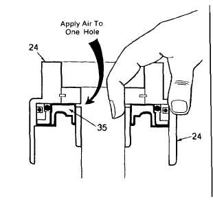
(26) Position spider gear assembly (24) on a
cloth on workbench as shown. Remove
piston (35) by applying compressed air to
one of the clutch oil passages in the spider
gear assembly. Plug the remaining hole
with index finger.
(27) Remove inner and outer block vee rings (33
and 34) from the piston (35).
(28) Inspect bearings (20 and 22) as detailed in
para. 2-7.
(29) If necessary, press damaged bearings (20
and 22) from drive shaft (30) if any damage
is evident. To remove bearing (20) it will be
necessary to remove lock ring (23) from
drive shaft.
b.
Inspection (1) Discard all O-rings, seals, and gaskets
WARNING
Dry cleaning solvent P-D-680 (safety or Stoddard’s solvent) is potentially dangerous. Avoid repeated and
prolonged breathing of vapors and skin contact with the liquid. Do not use near open flame, arcing equipment or
other ignition sources. Always wear eye protection and protective clothing. The flash point of P-D-680 is 100 to
138 deg. F (30 to 59 deg. C).
2-70
|