|
| |
TM 5-4210-220-34
3-8.
ENGINE - Continued
3-8.7
Gear Train - Continued
a.
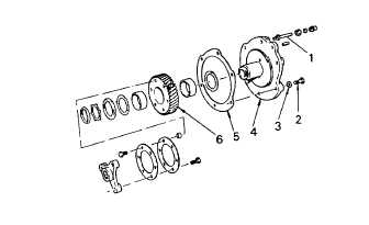
Blower Drive Gear Installation
NOTE
There are no timing marks on the blower drive
gear. Therefore it is not necessary to aline this
gear
in
any
particular
position
during
the
installation procedure.
(1)
Affix a new gasket (5) to the blower drive
gear support (4) and attach the gear and
support assembly to the cylinder block rear
end plate with capscrews (2) and copper
washers (3). Tighten the capscrews to 30 ft
lb (41 Nm).
(2)
ttach the lubrication line (1) to the blower
drive support (4).
(3)
Check the gear backlash between the blower drive gear (6) and the camshaft gear. To accurately check the
backlash, all of the flywheel housing attaching capscrews must be tightened to their proper torque, see para.
3-8.6. Backlash should be 0.002 0.008 in. (0.051 0.203 mm), and should not exceed 0.010 in. (0.254 mm).
(4)
Install the blower, see para. 3-8.3.
b.
Idler Gear Installation
(1)
Position the crankshaft gear and
the
camshaft gear so the timing marks will aline
with those on the idler gear.
(2)
With these marks aligned, start the idler
gear (5) into mesh with the crankshaft gear
and camshaft gear, and simultaneously
rotate the gear hub (3) so the dowel (4) in
the hub mates with the hole in the end
plate. Then, using a soft faced hammer,
gently tap the hub until it seats against the
end plate.
(3)
Secure the idler gear assembly to the
cylinder block using the special washers (2)
and bolt (1). Tighten the bolt to 90 ft lb (122
Nm).
(4)
Lubricate the idler gear bearing and gear teeth with engine oil (item 17, Appendix B).
(5)
After installation is complete, check the backlash between the mating gears. Allowable backlash for new
gears is 0.002 0.008 in. (0.051 0.0203 mm). Backlash must not exceed 0.010 in. (0.254 mm) for worn
gears.
3-146
|