|
| |
TM 5-4210-220-34
2-10.
PUMP BODY - Continued
2-10.1
Pump Body Assembly - Continued
NOTE
If the pump body is removed and
installed for the purpose of removing
hose body or agent tanks, disregard
steps (25 and 26) of this procedure and
steps (1 and 2) of the installation
procedure.
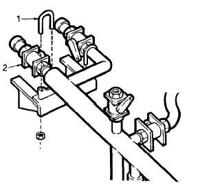
(25) Remove
four
clamps
(1)
attaching
discharge piping to pump body.
(26) Disassemble valves (2) (see TM 5-4210-
220-12) and remove discharge manifold,
valves, and discharge pipes from pump
body.
INSPECTION
(1)
Ensure that new pump body is free of
defects.
(2) Inspect structural control panel for damage and defects. Be sure wiring harness, and air and water lines are
free of defects and properly secured to control panel components.
(3) If control panel is replaced be sure the new panel is wired and plumbed identically to the one removed.
(4) Inspect discharge manifold and attaching components. Ensure that all items are undamaged and free of
defects.
INSTALLATION
(1) Position discharge manifold inside new pump body and assemble valves (2) (see TM 5-4210-220-12).
(2) Attach discharge manifold to pump body bracket using clamps (1).
(3) Attach lifting slings to pump body and hoist as in removal.
(4) Lift pump body onto truck carefully and aline mounting holes.
(5) Attach pump body to truck frame using four bolts and nuts. Remove lifting slings.
(6) Attach discharge manifold to pump discharge pipe using victualic coupling.
(7) Attach turret discharge pipe to manifold using victualic coupling.
(8) Thread hose reel heater hose up through body and attach to blower.
(9) Install PTO manual shutoff valve to left side of pump body. Install valve handle.
(10) Connect shop air line to air drier.
2-36
|

