|
| |
TM 5-4210-220-34
3-7.
TRANSMISSION-Continued
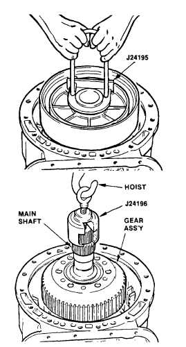
(2)
Install lifting bracket J24195 onto center
support and remove the support.
(3)
Remove the second-clutch snap ring.
Remove
the
second-clutch
plates.
Identify the pack and keep it intact.
(4)
Remove the four 1/8 in. cotter pins
Installed during gear and hub assembly.
CAUTION
Be sure all four cotter pins have been removed
from the rear planetary ring gear.
(5)
Install bearing race into the recess in the
front of the gear and hub assembly.
Retain it with petroleum jelly (item 21,
Appendix B).
(6)
Install bearing race and needle bearing
onto the hub of the rear carrier assembly
Retain them with petroleum jelly (item
21, Appendix B).
(7)
Attach lifting bracket J24196 to the main
shaft of the gear unit assembly. Attach
a hoist to the eyebolt on the lifting
bracket.
(8)
Lower the gear unit assembly engaging
the teeth of the four carrier pinions and
the Internal splines in the carrier hub
with the internal teeth of the rear ring
gear and external splines of the output
shaft respectively.
(9)
Install the 13 pre-selected second-clutch plates beginning with an external-tanged plate, and alternately
installing seven external-tanged and six internal-splined plates.
(10)
Install the white color coded snap ring or red color coded snap ring (if initial installation check called for
thicker snap ring) that retains the second-clutch plates. Be sure the snap ring gap is located at the top of
the transmission housing.
(11)
Install the third clutch piston assembly into the center support. The lips of the seal rings must be toward
the cavity in the center support.
Improper installation of butt-joint seal rings may cause transmission failure. If humidity is allowed to
penetrate and expand the butt-joint seal ring, the seal ring can be damaged during installation. A
damaged seal ring will leak oil from the clutch piston cavity and cause clutch3-75 slippage. Do not open
the sealed package until you are ready to install the seal ring.
3-75
|