|
| |
TM 5-4210-220-34
3-7.
TRANSMISSION-Continued
ac.
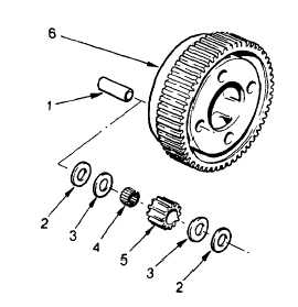
Low Planetary Gear Overhaul
(1)
Low planetary gear overhaul requires tools
J25587-1 Fixture
J25587-29 Pin Remover
J25587-7 (four) Loading Pins
J25587-47 (four) Guide Pins
J25587-36 Pin Installer
J25587-17 Swaging Tool Holder
J25587-21 Swaging Tool
J25587-4 Support Block
(2)
Drill out planetary pins drilled from rear side of carrier. Place carrier assembly in fixture with drilled pins
up. Install pin remover J25587-29 into fixture ram.
(3)
Press out four pins. Remove and keep four groups separate.
(4)
Inspect carrier (6) for excessive wear. Replace housing if damaged or worn excessively.
(5)
Install loading pin J25587-7 in each
pinion (5). Install roller bearing (4) on
pin,
then
steel
and
bronze
thrust
washers (2 and 3) on each end.
Lubricate
needle
bearings
with
transmission fluid (item 9, Appendix B)
before installation of groups into carrier.
(6)
Place carrier rear side up and place all
pinion groups into carrier. Install guide
pins J25587-47, large diameter first, in
place of loading pins.
(7)
Put carrier on fixture in press. Insert pin
installer J25587-36 into fixture ram.
CAUTION
Do not put pressure on the carrier. Distortion of
the carrier will damage it.
NOTE
Pin installers are shaped to avoid interference with bosses on the carrier assemblies. They must be
installed in the ram so that the cutaway portion of the installer will clear the bosses when the pinion pin is
pressed in.
(8)
Place a pinion pin (1) onto the pilot end of a pin guide in carrier. Press the pinion pin into the carrier until
the installer contacts the carrier.
(9)
Install the remaining pinion pins.
(10)
Remove the carrier assembly from the press fixture. Install swaging tool holder J25587-17 into 3-58 the
opening of the press fixture bed. Install a swaging tool J25587-21 into the holder. Install another swaging
tool J25587-21 into the press fixture ram. Lubricate both ends of the pinion pins with petroleum jelly (item
21, Appendix B).
3-58
|