|
| |
TM 5-4210-220-34
3-7.
TRANSMISSION - Continued
(10) Remove each driven gear shaft (19) (pump spindle) from the pump body, if necessary, using special tool set
J33080.
(11) Place puller assembly, puller bridge J33080-20 and collet J33080-4, over shaft to be removed with the legs of
the puller on the pump body.
(12) Tighten the collar locknut until collar is secured against collet and onto the shaft that is to be removed.
(13) Hold puller screw with wrench while tightening puller nut to remove shaft.
(14) To remove the shaft from collet, back off the collar locknut and puller nut. Position collar over retriever
J33080-2 and tap top of puller screw with a hammer to remove the shaft from the collet.
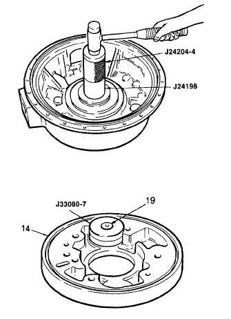
(15) Install new oil seal using seal installer J24198 , and driver handle J24204-4. Coat oil seal bore in pump body
with seal retainer (item 26, Appendix B). The lip of the seal must face inward (toward rear of transmission).
Seal should be flush with front of the housing
NOTE
Installer J24198 can be used with the
transmission assembled except for the
flywheel and torque converter.
(16) To install a new driven gear shaft (pump
spindle)
support
the
charging
pump
housing (14) in a press Position height
gage J33080-7 over the shaft bore and
place new shaft (19) into the gage so the
chamfer on the shaft will engage into the
housing bore.
(17) Press the shaft until flush with height gage.
The installed height of the spindle after
installation should be 0.926 - 0.885 in.
(23.52 - 22.48 mm).
(18) If needle bearing was removed from either
driven gear, install a new bearing. Place
the bearing, numbered end first, onto
installer tool J28646A. Attach handle
J8092. Install the bearing into driven gear.
(19) Install the driven gears (17) and the drive
gear
(20) into the oil pump body (14).
3-33
|

