|
| |
TM 5-4210-220-34
3-7.
TRANSMISSION - Continued
(5)
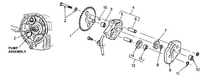
Remove snap ring (8) from the shaft of drive gear (1).
(6)
Remove driven gear assembly (12) from spindle (6).
(7)
Remove drive gear (7) from the shaft of drive gear (1). Remove lock roller(15)from the shaft of gear (1).
(8)
Remove gear (1) from pump body (4).
(9)
If replacement is necessary, press needle bearing (3) out of body (5). Press needle bearing (10) out of plate
(9).
(10) If replacement is necessary, press spindles (6) toward the inside of body (5).
Do not remove bushing (13) from gear (14) if proper machining procedure cannot be used at installation of
new bushing. Replace pump as an assembly.
(11) Remove damaged bushing (13) from scavenge pump driven gear (14).
(12) Press a new bushing into gear (14) to 0.030 in. (076 mm) below the surface of the gear.
(13) Check the ID of the bushing for runout. Runout must not exceed 0.001 in. (0.03 mm) Surface finish of the
bushing should be 30 microinch (0.762 micrometer).
(14) If spindles (6) were removed, install the spindles, plain ends first, into the inside of body (5). Press the
spindles to 1.0 in. (25.4 mm) above the inside surface of the body. Install driven gear (14) onto spindle (6).
3-19
|

