|
| |
TM 5-4210-220-34
2-21.
FRONT AXLE - Continued
(1)
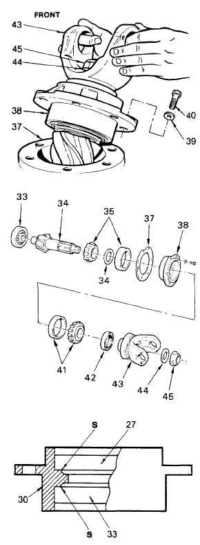
For front axle, remove nut (45), washer (44)
and yoke (43) from drive pinion; for rear
axle, remove helical gear (46) as detailed in
REPAIR procedure c. following.
(2)
Remove capscrews (40) and lockwashers
(39). Remove bearing cage (38) Record
number and sizes of shims (37).
(3)
Support bearing cage (38), and using a
press and suitable arbor, press pinion (34)
out of bearing cone (41).
(4)
Using a suitable tool, pry oil seal (42) free
of bearing cage (38) and discard.
(5)
Remove bearing cone (41) from bearing
cage.
(6)
Inspect bearings (33, 35, and 41) as
detailed in para. 2-7. If required, replace
bearing cones and cups as detailed in steps
8 thru 12 following. If bearings are
reuseable, proceed to step 13.
(7)
Remove and retain spacer (36).
(8)
Remove bearing cone (35) and pilot
bearing (33) from pinion (34) using a split-
type puller.
(9)
Remove bearing cups (35 and 41) from
bearing cage (38) using a suitable puller.
(10) Press new bearing cups (35 and 41) in
cage (38).
(11) Check space (S) using a feeler gage.
Bearing cups must be firmly seated with a
maximum clearance of 0.001 in. (0.03 mm)
between seat and race.
(12) Carry out preliminary pinion bearing preload
adjustment as detailed in ADJUSTMENT
procedure c.
(13) Press pilot bearing (33) on pinion (34) and
stake it in place.
(14) Install bearing cone (35) on pinion (34)
using a press. Install spacer (28).
(15) Install bearing cage (28) on drive pinion
(34).
2-295
|