|
| |
TM 5-4210-220-34
2-20.
REAR AXLE.
2-20.1
Power Divider (Transfer) Unit.
This task covers
a.
Removal
b.
Inspection
c.
Installation
d.
Repair
TOOLS
Wheels Blocked
Shop Equipment, Automotive
Pump and Hose Body Heat Shields Removed
Maintenance and Repair,
(see TM 5-4210-220-12)
NSN 4910-00-754-0705
Rear Axle Drive Lines Removed
(see TM 5-4210-220-12)
EQUIPMENT CONDITION
Air Tanks Drained
Main Engine Shutdown
(see TM 5-4210-220-12)
MATERIALS/PARTS
APU Engine Shutdown
10, Appendix B Dry Cleaning Solvent
(see TM 5-4210-220-12)
28, Appendix B Silicone Sealant
Batteries Disconnected
(see TM 5-4210-220-12)
NOTE
The power divider can only be replaced by replacing the individual components making up the unit.
Repair of the power divider is limited to replacement of components.
To facilitate power divider replacement or
major repair, the differential carrier should be
removed from the axle (see para. 2-20.2
REPLACEMENT) and placed on a work
bench/stand.
Minor
repairs
such
as
replacement of oil seals and drive shaft yokes
can be done with the power divider installed
on the axle, see REPAIR.
REMOVAL
NOTE
Differential carrier removed from axle.
a.
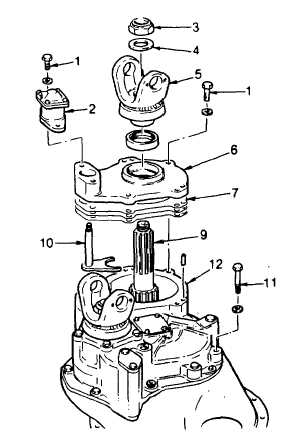
Output Shaft Removal.
(1)
Mount differential carrier in a repair
stand or support it on a low workbench
with the power divider facing up.
(2)
Remove nut (3), washer (4), and yoke
(5).
(3)
If not already done, remove capscrew
(1) and remove air shift unit (2), (see
TM 5-4210-220-12).
(4)
Lift and remove cover (6) and shims
(7). If cover binds, tap cover gently
with a soft mallet. Be careful not to
damage mating surfaces of covers (6
and 12).
2-266
|

