|
| |
TM 5-4210-220-34
2-19.
ENGINE - Continued
(10) Clean and examine all components. Replace either spring if cracked, worn, or pitted. If the reason for
removal was failure of the governor to control the engine, replace both springs.
(11) Inspect the spring seats for wear or corrosion. Replace as required.
(12) Place the high speed spring (13) on the plunger (14) with the loosely wound end of the spring against the
shoulder of the plunger.
(13) Insert the spring and plunger assembly into the spring retainer (11).
(14) Place the adjusting pin (10) in the hole in the plunger. Thread the idle speed adjusting screw (9) into the
threaded end of the plunger (14) about 1/2 in. (13 mm).
(15) Thread the locknut (8) onto the idle speed adjusting screw (9).
(16) Place the low speed spring (16) in the low speed spring cap (17) and the small end of the low speed
spring seat (15) into the opposite end of the spring.
(17) Insert the low speed spring assembly into the plunger (14) and over the idle speed adjusting pin (10).
(18) Insert the spring, plunger, and retainer assembly into the opening in the governor housing and thread the
retainer (11) into the housing approximately 1 in. (25 mm). Be sure the locknut (12) is installed on the
retainer.
(19) Adjust the governor as detailed in ADJUSTMENT preceding.
d.
Governor Weights and Bearing Repair
NOTE
Governor must be removed from engine
to carry out repair of the governor
weights and shaft assembly.
(1)
Remove governor from engine as
detailed in REMOVAL preceding.
(2)
Clamp the flange of the governor
housing (9) in a vise equipped with
soft jaws.
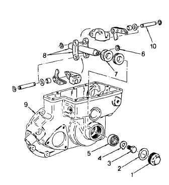
(3)
Unscrew and remove the plug (1) and
gasket (2). Discard the gasket.
(4)
Bend down the tang on the lockwasher
(4).
(5)
While preventing the weight carrier (8)
from turning, remove the bearing
retaining bolt (3), flat washer, and
lockwasher (4).
(6)
Thread a 5/16 - 24 X 3 in. bolt into the
bearing retaining bolt hole.
2-257
|

