|
| |
TM 5-4210-220-34
2-19.
ENGINE - Continued
2-19.13
Mechanical Governor - Continued
REPAIR
a.
Speed Control Shaft Repair
NOTE
This can be repaired with governor on engine.
(1)
Remove stop solenoid and throttle plate as detailed in para. 2-19.12.
(2)
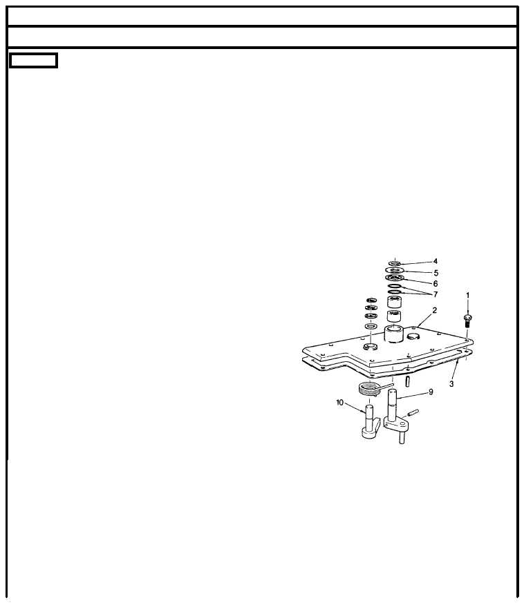
Remove screws (1) from cover (2), and pull cover from housing. Remove and discard gasket (3).
(3)
Remove snap ring (4), the two seal ring retainer washers (5 and 6) and the seal ring (7) from the shaft (9).
(4)
Withdraw shaft (9) from lower end of cover.
(5)
Inspect bearings and shaft. If bearings require replacement see steps 6 thru 15. If only the shaft requires
replacement go to step 16.
(6)
For bearing removal, remove stop shaft
(10) as detailed in Stop Control Shaft
Repair following.
(7)
Place the inner face of the cover over the
bed opening on an arbor press.
(8)
Place remover J21967-01 on top of bearing
and under the ram of the press.
(9)
Press both bearings out of the cover.
(10)
Lubricate the outside diameter of one of the
new bearings with engine oil (item 17,
Appendix B).
(11)
Start the bearing, number side up, into the
top face of the cover.
(12)
Press into position using a press and tool
J21068.
(13)
Place the cover, inner side up on the press and lubricate the second bearing with engine oil (item 17,
Appendix B).
(14)
Start the bearing, numbered side up, and press into positions as per the first bearing, but using the other end
of the installer, ie. this bearing remains flush with the face of the boss.
(15)
Install stop lever as detailed in Stop Control Shaft Repair following.
(16)
Lubricate the speed control shaft bearings with grease (item 16, Appendix B). Insert the speed control shaft
(9) through the bearings.
2-254
|