|
| |
TM 5-4210-220-34
2-19.
ENGINE - Continued
2-19.7
Exhaust Valves - Continued
(3) Tag and remove the injector fuel pipes from the
injector and fuel connectors.
(4) Cover each injector opening and the fuel pipe
openings with shipping caps to prevent the entry of
foreign material.
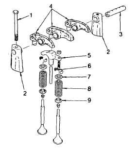
(5) Remove the two bolts (1) holding the rocker arm
shaft brackets (2) to the cylinder head. Then
remove the brackets and shaft (3)
(6) Flip over the rocker arms (4) and lift off the exhaust
valve bridge (5).
(7) Remove the cylinder block air box cover so that
piston travel may be observed, then turn the
crankshaft until the piston is at the top of its stroke.
(8)
Thread the valve spring compressor adaptor J7455
into the rocker arm bracket bolt hole in the
cylinder head. Compress the valve spring and remove the two-piece tapered valve lock (6).
(9) Release the tool and remove the spring cap (7), valve spring (8), and spring seat (9).
b.
Exhaust Valve Removal
NOTE
Cylinder head must be removed, see para. 2-19.8. The following instruction may be used for the right
hand or left hand cylinder head.
(1) Support the cylinder head on 2 in. thick wood blocks to keep the cam followers clear of the bench. Be
careful not to damage or scratch the seal area around the intermediate water nozzles.
(2) Remove the fuel pipes from the injector and fuel connectors. Cover the fuel pipe and injector openings with
shipping caps to prevent entry of foreign material.
(3) Remove the two bolts (1) holding the rocker arm shaft brackets (2) to the cylinder head. Remove the
brackets (2) and shaft (3).
(4) Remove the fuel injectors as detailed in para. 2-19.5.
(5) Flip over the rocker arms (4), and lift off the exhaust valve guide bridge (5).
(6) Place a block of wood under the cylinder head to support the exhaust valve being removed.
(7) Thread the valve spring compressor J7455 into the rocker arm bracket bolt hole in the cylinder head.
2-206
|

