|
| |
TM 5-4210-220-34
2-19.
ENGINE - Continued
2-19.7
Exhaust Valves.
This task covers:
a.
Adjustment
b.
Removal
c.
Inspection
d.
Installation
e.
Repair
TOOLS
Top Exhaust System Elbow Removed
Shop Equipment, Automotive
(see TM 5-4210-220-12)
Maintenance and Repair,
Both Rocker Covers Removed (see para. 2-19.3)
NSN 4910-00-754-0705
J22582 Engine Barring Tool
MATERIALS/PARTS
J7455 Valve/Spring Removal Tool
10, Appendix B Dry Cleaning Solvent
J9708-01 Feeler Gage
15, Appendix B Gear Oil
J22738-02 Spring Tester
17, Appendix B Engine Oil
J5437 Valve Guide Brush
18, Appendix B Masking Tape
J8932-01 Fuel Pipe Socket
5149510 Rocker Cover Gasket
J25076-B Spring Checking Gage
5147347 Exhaust Valve Spring
8921209 Exhaust Valve Guide Seal
5149041 Exhaust Valve Kit
EQUIPMENT CONDITION
Main Engine Shutdown (see TM 5-4210-220-12)
APU Shutdown (see TM 5-4210-220-12)
PERSONNEL REQUIRED - 2
Batteries Disconnected (TM 5-4210-220-12)
LH and RH Engine Covers Removed
(see TM 5-4210-220-12)
ADJUSTMENT
NOTE
This is the first task in any tune-up.
Exhaust valve bridge is adjusted during valve installation; the push rod only is adjusted after the engine is
rebuilt. Rocker must be removed as detailed in para. 2-19.3.
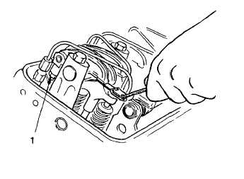
(1) Cover any drain cavities in cylinder head to
prevent foreign material entering.
(2) Allow engine to cool completely; must be
less than 100 deg. F (38 deg. C).
(3) Ensure governor speed control lever is in
the idle position and stop lever is in the stop
position. This is the normal setting when
engine is shutdown.
(4) Remove starter motor and install barring
tool J22582 (see TM 5-4210-220-12 for
starter motor removal) or barr engine using
starter motor or wrench on the crankshaft
pulley bolt (if using wrench, do not rotate
engine in left-hand direction because this
may loosen the bolt).
2-204
|