|
| |
TM 5-4210-220-12
4-32. FRONT AXLE - Continued
NOTE
If axle shaft assembly is removed for any reason
other than replacement, it should be thoroughly
inspected before reuse.
(5) Check shaft splines for damage, cracks, or wear.
Check shaft journal for scoring or excessive
grooving. Check that yoke trunnions are not
excessively loose in cage rings. Replace axle
shaft assembly if faulty or damaged.
(6) To measure exact clearance between axle yoke
trunnions and cage ring holes, the axle shaft may
be disassembled and the components checked as
detailed in steps 7 thru 10 following.
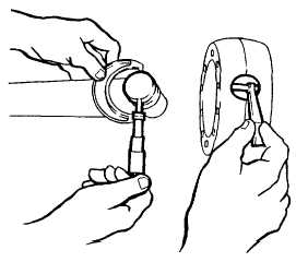
(7) Punch mark trunnions and cage rings as shown. To
ensure correct operation of axle shaft, the
trunnions must be replaced in the original cage ring
holes.
(8) Measure yoke trunnions and cage ring holes as
shown. If the clearance between corresponding
ring holes and yoke trunnions exceeds 0.050 in.
(1.25 mm) replace axle shaft assembly.
(9) If axle shaft assembly is reuseable, lubricate
journals with grease (item 16, Appendix E) and
reassemble components in exactly same positions
as before disassembly.
(10) Rotate the shaft and be sure the trunnions move
freely during a full revolution with the axle shafts
forming an angle of 30 deg.
(11) Be sure ball socket (4) is in straight ahead position
and grease axle shaft bushing. Pack inner walls of
axle ball with 3/4 in. (75 mm)! layer of grease (Item
16, Appendix E).
(12) Inspect axle shaft (5) and remove any nicks and
burrs to prevent damaging oil seal inside axle ball
when installing shaft assembly in housing.
(13) Carefully install axle shaft assembly. Be sure cage
rings are completely coated with grease when the
shaft is inserted in housing.
(14) Install brake spider (3) and spindle (2) using
capscrews (1). Tighten capscrews to 220 ft lb (300
Nm).
4-601
|