|
| |
TM 5-4210-220-12
4-32. FRONT AXLE - Continued
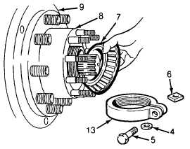
(3) Remove clamp screw (5) and lockwasher
(4) from wheel bearing adjusting nut (6).
This will release the nut lock Remove lock
(13) then unscrew and remove bearing
adjusting nut.
(4) Remove wheel outer bearing cone (7).
NOTE
If bearing cone is not to be
replaced identify its location so it
can be returned to its original
position.
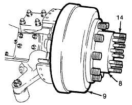
Generally brake drum and hub may be left
assembled.
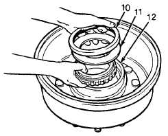
(5) Remove wheel hub (8), and drum (9)
assembled. To disassemble hub, remove
oil seal (10) and spacer (11) then lift out
inner bearing cone (12).
(6) Inspect bearing cones and cups for pitting,
wear or other faulty condition. If bearing
replacement is necessary, remove cup
from hub using suitable puller. Replace
bearings in sets (cup and cone).
(7) Inspect brake drum (9) for cracks,
discoloration due to hard spots, heat
checking, glazing, grooving or severe
out-of-round condition. Replace cracked
drums.
(8) Inspect hub (8) for damage. Replace hub if
faulty.
(9) If new hub is required, install new studs (14)
in hub. Apply antiseize compound (Item 3,
Appendix E) to studs before installation.
(10) If bearing cups were removed from hub,
install with suitable driver. Install cups until
they seat firmly against shoulder inside
hub.
(11 ) Line entire wall of hub with grease (Item
16, Appendix E). Fill hub with grease
leaving only an opening large enough for
the spindle to pass through.
(12) Pack bearing cones with grease (Item
16, Appendix E). Install inner bearing cone
(12) in hub. Install bearing spacer (11 ) on
cone with chamber (at inner diameter)
facing out.
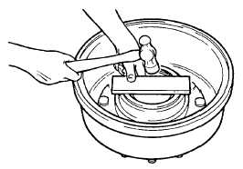
(13) Install oil seal (10) in hub using suitable
driver or press. Press seal in until. It is
flush with face of hub.
4-597
|