|
| |
TM 5-4210-220-12
4-30. REAR AXLE - Continued
4-30.5 Air Shift Units - Continued
b.
Differential Lock Air Shift Unit Repair Continued
(9)
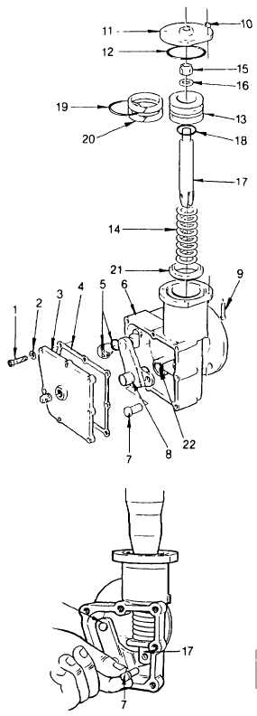
Inspect housing and cover bearing bushings
(22). Replace bushings if these are heavily
worn or scored.
(10) Inspect piston (13). Replace if friction
surface
shows
excessive
wear,
deep
scoring, or other damage.
(11) Inspect push rod (17) and replace if thread
is stripped, clevis pin holes are elongated,
or rod otherwise damaged.
(12) In preparation for installation, soak new felt
oilers (20) in Dexron (item 9, Appendix E)
and lubricate O-rings (5, 12, and 19) with
petroleum jelly (item 27, Appendix E).
(13) Lubricate
bearing
bushings
(22)
with
Dexron (item 9, Appendix E) and install
actuating lever and pin (8), assembled as
shown, in shift unit housing.
(14) Install piston (13) and O-ring (18) on push
rod (17) and secure with washer (16) and
locknut (15). Tighten locknut to 150 in. lb
(17 Nm).
(15) Install felt oilers (20) and O-ring (19) on
piston (13).
(16) Insert piston stop (21), compression spring
(14) and the assembled piston and push rod
in shift unit housing. Be sure clevis end of
push rod (17) lines up with actuating lever
(8).
(17) Using a press, carefully push piston into
housing bore. As the push rod (17)
protrudes the spring stop bracket, make
sure push rod clevis straddles actuating
lever arm (8).
(18) Aline clevis pin holes in push rod and
actuating lever and install clevis pin (7).
(19) Apply gasket eliminator (item 14, Appendix
E) to capscrews (1).
4-580
|