|
| |
TM 5-4210-220-12
4-30. REAR AXLE - Continued
4-30.4 Brake Assembly - Continued
(7) If disconnected, connect truck batteries and
start engine. Run engine until air system is
at normal pressure.
(8) Stop the engine and disconnect truck
batteries.
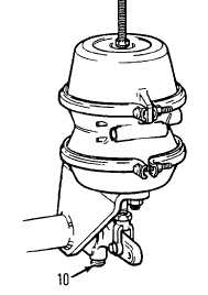
(9)
Push locking sleeve on slack adjuster down
and turn adjustment screw (10) clockwise
until brake shoes are tight against brake
drum.
(10)
Back screw (10) off approximately two
turns, 10-12 flats on the screw head, until
there is no brake drag.
(11)
Be sure locking sleeve engages adjuster
screw (10) when adjustment is completed.
(12) To be sure brakes are free and without drag, tap brake drum with a hammer and listen for a clear
ringing sound, or turn the wheel in forward and reverse directions and check brake shoes do not
rub against brake drum.
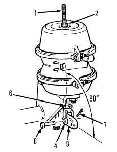
(13) Apply the rear brakes using the brake pedal in the cab. Check the angle between air chamber push rod
and slack adjuster as shown. The angle should be 90 deg. If the angle is less, or more than a few
degrees larger than this, adjust position of clevis (4) on push rod (5).
(14) To adjust position of clevis loosen jam nut
(6).
(15) Remove clevis pin (8) and disconnect
clevis (4) from slack adjuster (9).
(16) Turn clevis (4) as required to increase or
decrease overall length of push rod.
(17) Secure clevis pin using cotter pin (7) and
tighten jam nut (6) against clevis.
(18) Recheck angle between slack adjuster and
push rod as detailed in step 10 above.
(19) Apply parking brake by removing nut (2),
and twisting stud (1) out of engagement
with spring retainer. Remove stud from
brake chamber.
(20)
Install stud and nut in storage position on side of brake chamber. Tighten nut securely.
(21)
Install protection plug in brake chamber opening.
(22) Repeat steps 2 thru 21 for second rear brake. When complete, lift axle with jack and remove
maintenance trestles.
4-568
|