|
| |
TM 5-4210-220-12
4-26. DRIVE LINES, POWER TRAIN - Continued
4-26.4 Universal Joint - Continued
ASSEMBLY
(1)
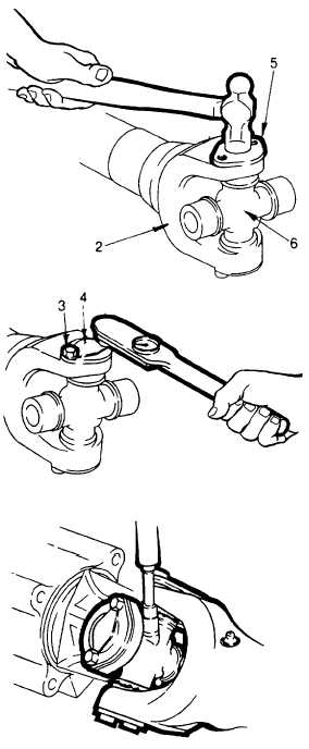
Install the cross in yoke so that cross
journals are positioned in yoke lugs.
Grease fitting in cross must be towards
shaft.
(2)
Install the bearing plate (5). Push journal
of cross (6) through the yoke lugs and into
needle bearing in bearing plate.
(3)
While supporting the cross to prevent
separation of cross and bearing, use a
hammer to lightly tap bearing plate (5)
into place in the yoke (2).
(4)
Install lockstrap (4) and capscrews (3).
Fingertighten capscrews.
(5)
Rotate drive shaft yoke to facilitate
installation of the second bearing plate.
(6)
Carefully
install
bearing
plate
onto
opposite side of the cross similar to
procedure in steps 2 thru 4.
(7)
Tighten capscrews to 40 ft lb (54 Nm).
While tightening, move cross back and
forth to ensure that it does not bind in the
needle bearings.
(8)
Using a hammer and chisel, bend up the
lockstrap ears to secure capscrews.
(9)
Install drive shaft see para. 4-26.3.
(10)
When all bearing plates are installed and
drive shaft is in place, lubricate the
universal joints until grease (item 16,
Appendix E) is expelled from all four
bearing plate seals.
4-512/(4-513 Blank)
|

