|
| |
TM 5-4210-220-12
4-26. DRIVE LINES, POWER TRAIN - Continued
REMOVAL
NOTE
Disconnect rear drive shafts and differential end of front drive shaft with the universal joint
crosses attached to shaft. Disconnect front drive shaft with U-joint cross to rear drive shaft
remaining attached to rear shaft.
a.
Drive Shaft Removal.
(1)
If the drive shaft universal joint locking screws and straps are corroded, apply penetrating oil (item 20,
Appendix E) to ease disassembly.
(2)
Mark all yokes and slip joints before removal. This will ensure alinement of components during installation.
(3)
Using a hammer and chisel bend down the ears on the two lockstraps (2) attached to the yoke opposite the
drive shaft to be removed (e g (7) in illustration).
(4)
Remove capscrews (1) and lockstraps (2).
CAUTION
Do not use jack method to
disassemble U-joint between front
and rear drive as this may cause
damage to the center bearing.
Unless special puller (Kent Moore
J36138) is available, disconnect
front and rear drive shafts at
differentials and detach center
bearing from frame. Disassemble
drive shafts on floor where shafts,
yokes, and center bearing can be
supported.
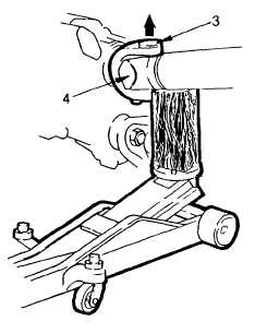
(5)
Turn the yoke until the bearing plates (3)
are vertically alined. If necessary, raise
the front or rear axle as detailed in para.
4-9.
(6)
Using a floor jack and a block of wood,
jack the wooden block up until it contacts
the drive shaft end yoke (4) as shown.
(7)
Continue to jack the block up until it
forces the upper bearing plate (3) out of
the yoke.
(8)
Once the upper bearing plate has been
removed, lower the jack and rotate the
shaft a half turn. Remove the second
bearing plate similar to steps 5, 6, and 7.
4-503
|