|
| |
TM 5-4210-220-12
4-25 STEERING SYSTEM - Continued
(6)
Install link end (9) to ball (10) and turn
steering wheel until drag link just pushes
on ball without moving front wheels.
(7)
Hold steering wheel so that contact of ball
and drag link is maintained and check
position of pitman arm. The arm should
be at right angles to the steering gear axis
(A).
(8)
Repeat steps 5 and 6 until condition in
step 7 is satisfied.
(9)
Replace dust shield (8) over axle ball (10)
and install plug (4) to link end (9). Install
link end on ball (10).
(10)
Tighten plug (4) until it bottoms against
ball, then back off until cotter pin (2) can
be installed. Install and secure cotter pin.
(11)
Tighten nut (11) securely.
(12)
Tie dust shield around the link end.
(13)
Lubricate both ends of the drag link with
grease (item 16, Appendix E).
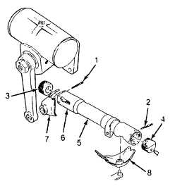
REPLACEMENT.
(1)
Remove cotter pin (1) and plug (3). Pull
link end (6) off pitman arm ball. Turn
steering wheel slightly if necessary, to aid
the removal. Remove dust shield (7).
(2)
Remove cotter pin (2) and plug (4) and
remove complete drag link (5) from truck.
(3)
Inspect new drag link and preadjust it to
same length as the one removed.
NOTE
Nominal center-to-center distance
between pitman arm and steering
linkage balls is 22 7/8 in. (581
mm).
(4)
Install a new dust shield (7) and link end
(6) on pitman arm. Screw plug (3) into
link until it bottoms against ball, then back
off until cotter pin (1) can be installed.
Install and secure cotter pin.
(5)
Adjust and complete drag link installation
as detailed in ADJUSTMENT preceding
4-485
|