|
| |
TM 5-4210-220-12
4-24 ELECTRICAL SYSTEM - Continued
(4)
While holding pot, unscrew wires to lamp from terminal block. Note which color wire is attached
to which terminal.
(5)
Attach wires of new lamp to terminal block as noted in step 4.
(6)
Apply a 1/8 in. (3 mm) bead of sealant (item 25, Appendix E) around the edge of the cab panel
hole.
(7)
Offer up new lamp pot to cab and secure with eight screws. Tighten securely.
NOTE
The lamp pot and its flange form part of the cab envelope. Be sure sealant is spread all round flange to
prevent entry of water to cab (8). Install sealed beam as detailed in a. preceding. Before installing cab
bumper aline new lamp as detailed in ALINEMENT.
ALINEMENT
NOTE
Two people will be required to carry out this alinement. To ensure correct alinement front
bumper should be removed, see para. 4-10.1.
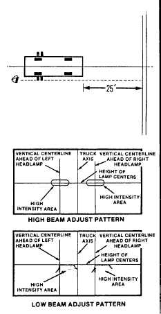
(1)
Park truck on a level floor 25 feet (7.6 m) away
from a light colored vertical screen or wall.
(2)
Open both rear doors on the middle row of the
hose body compartments.
(3)
Sight down both doors on one side of the truck
and mark this point on the screen. Repeat for the
other side of the truck.
(4)
Draw a vertical line on the screen at the midpoint
between the two sight marks.
(5)
Measure the distance, center to center, between
the two head lamps. Divide this distance by two
and draw two vertical lines, at this distance from
the vertical center line, one each side.
(6)
Measure the vertical height between the floor
and the center line between the headlamps.
Mark a horizontal line on the screen at this same
height.
4-445
|