|
| |
TM 5-4210-220-12
4-24. ELECTRICAL SYSTEM - Continued
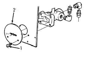
(4)
Remove screws (1) and face plate (2).
(5)
Lift switch from back of panel.
(6)
Install fittings in switch. Coat thread with pipe sealant, (item 22, Appendix E) prior to installation.
(7)
Install switch in panel. Retain with screws (1) and face
(8)
Install air lines as tagged in step 2 preceding.
(9)
Install air panel on instrument panel frame.
c.
Toggle Switch (Fold-Down Panel) Replacement
NOTE
These switches are Single-Pole-Single-Throw (SPST), Single-Pole-Double-Throw (SDT) or Double-Pole-
Double-Throw (DPDT). They are installed similarly. Theses switches are used to operate all the truck lights
(except panel lamp), the heated mirrors, the heater and defroster fans and the fire pump.
The fir pump switch 8201K6 has a guard (8499K1) over the top to prevent inadvertent operation. The guard
and switch are mounted using two screws rather than the toggle nut outlined in the following. Otherwise
replacement is the same as detailed following. The headlamp switch is a push-pull. Remove knob prior to
remove, otherwise replacement is the same as detailed following.
(1)
Hinge up the fold-down panel as detailed in para. 4-24.4 paragraph c.
(2)
Tag and disconnect wires from failed switch.
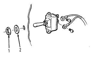
(3)
Unscrew nut (1) from front face of panel. Remove nut (1) and lockwasher (2).
(4)
Pull switch from rear of panel and discard.
(5)
Install new switch in panel hole. Be sure terminal mounted in middle of switch block has screw head
pointing to the right. Check pump switch has open contacts when switch is pointing upwards).
(6)
Install washer (2) and nut (1). Tighten firmly.
(7)
Reconnect wires as tagged in step 2 preceding.
(8)
Fold back panel and install retaining screws.
4-433
|