Order this information in Print

Order this information on CD-ROM

Download in PDF Format


Click here to make tpub.com your Home Page

Page Title: REPLACEMENT (cont)
Back | Up | Next

Click here for a printable version

Google


Web
www.tpub.com

Home


Information Categories
.... Administration
Advancement
Aerographer
Automotive
Aviation
Combat
Construction
Diving
Draftsman
Engineering
Electronics
Food and Cooking
Math
Medical
Music
Nuclear Fundamentals
Photography
Religion
USMC
   
Products
  Educational CD-ROM's
Printed Manuals
Downloadable Books


TM 5-4210-220-12 4-24 ELECTRICAL SYSTEM - Continued (7) 
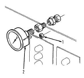
Remove nuts (1) and clamp (2) and lift gage from panel. (8) Remove fitting from gage. (9) Install fitting on new gage.  Coat threads with pipe sealant (item 22, Appendix B) prior to installation. (10) Install new gage in panel.  Ensure bezel fits snugly against plate. (11) Install new nuts (1) and clamp (2).  Tighten nuts. (12) Connect water line to gage as tagged. (13) Fold back instrument panel and retain with 12 machine screws. (14) Start main engine and fire pump as detailed in.  Chapter 2 (CFR or structural mode). (15) Check pressure gage or level monitor function correctly. 4-429

Privacy Statement - Press Release - Copyright Information. - Contact Us - Support Integrated Publishing

Integrated Publishing, Inc. - A (SDVOSB) Service Disabled Veteran Owned Small Business