|
| |
TM 5-4210-220-12
4-23. FUEL SYSTEM AND AIR INTAKE - Continued
4-23.5 Fuel Pump - Continued
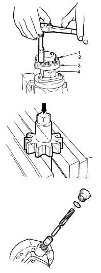
(5)
Remove eight cover bolts (1) and lockwashers (2). Withdraw pump cover (3) from pump body (4). Take
care not to damage machined faces of either component.
(6)
Pull up drive shaft and withdraw shaft with attached gear from fuel pump body.
(7)
Insert drive shaft, non-square end, into vise jaws. Vise jaws should not bear on shaft. Press square end, if
necessary tapping with soft hammer, until the gear is pressed beyond the gear retaining ball detent.
(8)
Remove ball.
(9)
Invert drive shaft in vise jaws and press gear from drive shaft. Gear must be withdrawn from non-squared
end of shaft.
(10)
Pull out the driven shaft and gear from the pump body. The gear cannot be withdrawn from the driven
shaft.
(11)
Remove relief valve plug and copper gasket. (Take care not to allow spring to jump out of assembly.
Remove plug slowly with socket wrench so spring cannot escape).
(12)
Lift/shake out valve spring, pin and relief valve from cavity in pump body.
4-402
|