|
| |
TM 5-4210-220-12
1-17. BRAKE SYSTEM - Continued
b. Rear Brake System
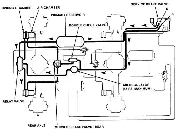
(1) When the brake pedal is depressed, pilot pressure is supplied from the primary reservoir via the service
brake valve and regulator to the relay valve, (see fig. 1-31). The pilot pressure opens the relay valve and allows brake
application air from the primary reservoir to enter and pressurize the spring brake chambers. The combined force of air
and spring pressure suppresses the parking brake release pressure in the opposing air chambers, (see para. 1-17 a.) and
engages the brakes.
(2) To prevent excessive brake force, the continuously balanced pilot and spring chamber air pressures are
regulated to a maximum 45 psi (see 310 kPa) Below this limit the pressures are infinitely controlled.
(3) When the brake pedal is released, the pilot pressure is exhausted. The relay valve shuts off the brake
application air and vents the spring chambers to atmosphere. The opposing air chambers remain pressurized and thus
disengage the brakes.
(4) To prevent jamming of the brakes if the service brakes are applied while the parking brakes are engaged,
counteracting pressure is provided to the air chambers. This air pressure is provided via the double check valve and
quick release valve simultaneously with the application of air pressure to the spring chambers.
Figure 1-31. Rear Brake System - Normal Operation
1-37
|

