|
| |
TM 5-4210-220-12
4-23. FUEL SYSTEM AND AIR INTAKE - Continued
(9)
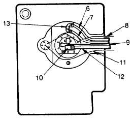
Remove winterization and main engine
fuel return lines (6 and 7) and cap the
ends.
(10)
Tag
and
remove
winterization
fuel
delivery line (9) and cap the end.
(11)
Tag
and
remove
main
engine
fuel
delivery line (11) and cap the end.
(12)
Tag and remove grounding wire (8), fuel
priming pump wire (10) and fuel level
sender unit wire (12).
(13)
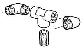
Remove pipe fittings (13) from fuel return
opening on tank (Includes close nipple,
tee and two elbows).
(14)
Remove four capscrews, flatwashers and
lockwashers attaching tank to bottom of
compartment.
(15)
Slide fuel tank out of side of fuel tank compartment.
INSPECTION
(1)
Check fuel tank for signs of cracking or
leaks. Check inserts in bottom of tank are
undamaged and threads are clean. If fuel
tank is damaged, refer to Direct Support
Level for repair.
(2)
Check fuel return insert is undamaged
and threads are clean.
(3)
Inspect all fittings for damaged threads, or
cracked bodies. Replace as required.
(4)
Clean
and
inspect
all
electrical
connections. Coat all connectors with
white grease (item 34, Appendix E).
INSTALLATION
(1)
Slide fuel tank through side of fuel tank compartment until mounting fasteners in tank line up with holes
in bottom of compartment.
(2)
Install four capscrews, flatwashers, and lockwashers and torque to 30 ft lbs (41 Nm).
(3)
Coat all pipe threads with pipe sealant (item 22, Appendix E) and rebuild the return assembly on the
tank. The arms of the elbows should be horizontal and point towards the hose duct on the engine side of
the tank.
4-391
|