|
| |
TM 5-4210-220-12
4-22 AIR SYSTEM - Continued
(3)
Ease valve body through cab floor.
(4)
Seal area around flange with sealant (item 25, Appendix E) and install screws (1) to secure valve to cab
floor.
(5)
Start main engine and ensure foot throttle provides increase in engine speed in proportion to treadle
depression. Ensure engine cuts back to low idle immediately treadle is released.
(6)
Stop main engine and disconnect batteries.
(7)
With treadle depressed about half way, brush soap solution over entire valve assembly and connectors.
No leakage is permitted. Tighten/remake joints as required. Ensure this bubble test is carried out with
primary air tank at greater than 65 psi (450 kPa).
REPAIR
a.
Treadle Repair
NOTE
This can be repaired without removing
whole foot throttle valve from truck.
(1)
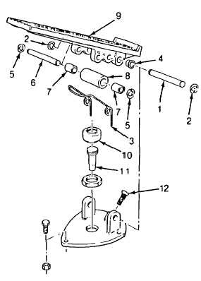
Remove spring clip (2), pin (1), pedal (9),
and spring (3).
(2)
Tap bushings (4) out of pedal.
(3)
Remove spring clip (5), pin (6), bushings
(7), and roller (8).
(4)
Remove dust boot (10) and push rod (11).
(5)
Inspect all parts for wear, or stiffness.
Replace any parts failing inspection.
NOTE
Item 1 thru 8 are available in the
repair kit. This kit also includes parts
to repair the valve subassembly.
(6)
Lubricate both pivot pins and push rod with silicone grease (item 27, Appendix E).
(7)
Install push rod (11) in valve. Install dust boot (10) over push rod. Be sure dust boot engages in housing
and on push rod.
(8)
Put bushings (7) in roller (8). Slide pin (6) through pedal and roller bushing and retain with clips (5).
(9)
Install bushings (4) in valve housing.
4-371
|

