|
| |
TM 5-4210-220-12
4-22. AIR SYSTEM - Continued
(4)
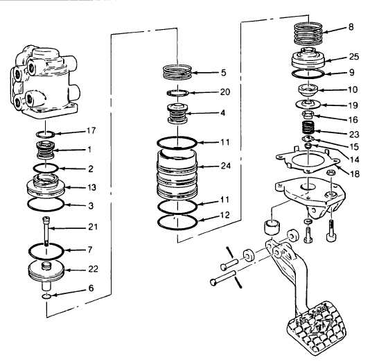
Insert blade of screwdriver through relay piston exhaust passage into slot of stem (21), and remove locknut
(14) being careful not to nick the exhaust seat of the relay piston.
(5)
Remove locknut, spring seat (15), stem spring (23), spring seat nut (16), rubber spring seat (19), and
rubber spring (10).
(6)
Relay piston (22), relay spring (5), and stem bolt (21) may now be removed.
(7)
Removal of screwdriver or wire from locking groove will permit spring load to push the No. 1 circuit piston
(25) from the lower static piston (24) Care should be used when removing tool from locking ring because of
spring load.
(8)
Remove O-rings (6 and 7) from relay piston and O-ring (9) from No 1 circuit piston (25).
(9)
Remove O-rings (11 and 12) from lower static piston.
(10
Remove large retaining ring (20) from lower static piston and remove No. 1 circuit inlet/exhaust valve
assembly (4).
4-365
|

