|
| |
TM 5-4210-220-12
4-22. AIR SYSTEM - Continued
(6)
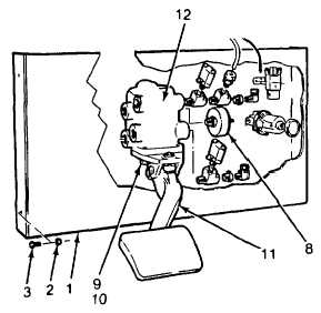
While supporting the brake valve, remove the three capscrews (12) attaching brake pedal to plate.
(7)
Remove all fittings and pressure switches attached to the valve.
(8)
To remove the valve internals carry out the following instructions.
(9)
Remove capscrews (9) and washers (10) Remove brake pedal assembly (11).
(10)
Pry off retainer plate mounted beneath valve block. This plate may come off as brake pedal assembly is
removed.
(11)
Pull out the lower static piston assembly from the body (12).
(12)
Make a hook using a piece of wire and insert wire into body. Hook remaining valve assembly and pull
firmly to remove assembly from body (12).
INSTALLATION
(1)
Push upper static piston into valve body.
(2)
Push lower static piston into valve body and
retainer. Ensure locking tabs of retainer
plate engage valve body.
(3) Install pedal assembly (11) using three
capscrews (9) and washers (10).
(4)
Install all fittings and pressure switches in
valve body using illustration as a guide. Do
not install stop light switches (8). Coat all
pipe threads with pipe sealant (item 22,
Appendix E) prior to installation.
(5)
Support the valve and attach the brake valve to the plate (1) using capscrews (7).
(6)
Replace hoses (D, E, F, and G) to the back of the brake valve. Be sure they are connected exactly as
noted in REMOVAL, step 4.
(7)
While supporting the plate (1) Install the six screws (3) and locknuts (2).
(8)
Install bolts (4) and nuts (6) to reattach steering support brackets (5) to brake pedal plate (1).
(9)
Reconnect hoses (A, B, and C) to the front of the brake valve. Be sure they are connected exactly as
noted in REMOVAL, step 2.
(10)
Connect a temporary 0 - 150 psi (0 - 1000 kPa) gage to each of the brake stop switch ports.
(11)
Start main engine and allow all air tanks to reach full pressure.
4-363
|