|
| |
TM 5-4210-220-12
4-22 AIR SYSTEM - Continued
(5)
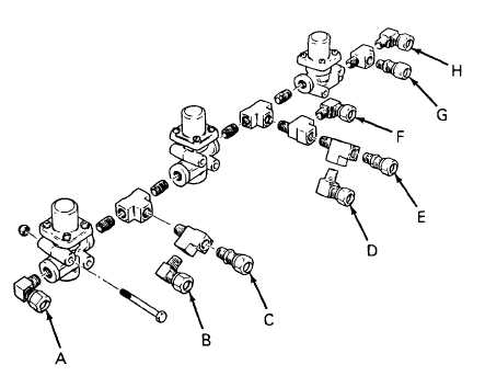
Slowly build up the pressure in line D to 90 psi (620 kPa) maximum
(6)
Brush all connections with soap solution. Tighten or remake connections as required.
(7)
When all leaks are repaired, release all pressure by venting ports A, C, and H
(8)
Refill line D very slowly with air to a maximum of 90 psi (620 kPa)
(9)
Monitor the pressure gages and note the pressure at port D when the other gages start to show an
increase in pressure. (Port A will only show pressure when the space between the two pressure protection
valves is at pressure.)
(10)
All valves should have a pressure setting of 85 psi (500 kPa) Adjust the pressure setting by loosening the
locknut (1) and tightening or loosening the adjusting cap (2) as required
(11)
When all valves are set, remove pressure gages, drain valves, blanks, and temporary air lines
(12)
Mount manifold on cab cross member using the six machine screws and locknuts
(13)
Connect the truck air lines to the manifold. Be sure they are in the same location as noted in step 1 of
REMOVAL preceding
REPAIR
NOTE
The pressure protection valves cannot be repaired. If faulty, replace
4-343
|