|
| |
TM 5-4210-220-12
4-19. WINTERIZATION SYSTEM - Continued
INSTALLATION
(1)
Carefully lift heater through pump body access door and place in position on the support brackets.
(2)
Aline heater on brackets and tighten capscrews (8) and locknuts (7).
(3)
Attach exhaust pipe (7) to heater and tighten clamps.
(4) Push fuel lines on to connectors and tighten hose clamps. Fuel inlet line is on left hand side of
heater looking at motor end.
(5) Push water hoses and connectors and tighten hose clamps. Water inlet line is on left hand side and
is nearest port to motor.
(6)
Reconnect electrical plugs (6) to heater.
(7) Close valve on radiator and fill radiator. If hose crimp retaining pliers were used to isolate the
heater, remove the pliers.
(8) Start APU and circulate water through winterization system topping up radiator as required. Check
all connections for leaks. Tighten/remake as required.
(9) While APU is running, loosen connection on pump body heater outlet and bleed air from top of
heater. Retighten hose clamp.
(10)
Top up radiator as required and replace radiator cap.
(11) Start winterization heater (see para. 2-12). Check heater fires up and brings temperature of coolant up
to a steady 50 deg. F (10 deg. C).
(12)
Stop winterization system (see para. 2-12).
(13)
Replace pump body panel.
REPAIR
a.
Electronic Control Unit Repair
NOTE
This can be replaced without
removing heater from truck.
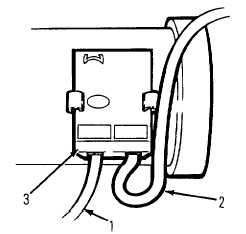
(1)
Disconnect wiring harness plugs (1, 2) from
control unit.
(2)
Unclip control unit from side of motor (3)
and replace. The electronic control unit
cannot be repaired.
(3)
Refit all plugs into electronic control unit.
4-301
|