|
| |
TM 5-4210-220-12
4-18. PUMP, PIPING, AND VALVES - Continued
(10) Inspect seal washers for deterioration. Replace parts as necessary.
(11) Prepare new cable for installation as shown. Install upper nut (5) and upper seal washer (6) onto new
cable conduit (4). Ensure that only one nut is on the nozzle end of the cable. Remove all hardware and
fasteners from control handle end of cable.
(12) Install nozzle end of cable into the sleeve boss and install lockwasher (9) and nut (8). Tighten nut
firmly.
(13) Attach cable (4) to cable mounting plate (12) using conduit clamp (11), machine screw (10), and
lockwasher (9) as shown. Do not tighten screws.
(14) Install control handle end of cable through opening in base plate (7).
(15) Install lower seal washer (6) and lower nut (5) onto cable conduit as shown. Tighten lower nut (5) firmly.
(16) Install jam nut (3) onto control handle end of cable (4).
(17) Thread end rod ball joint (1) onto cable the same number of turns as recorded in step 3 preceding.
(18) Install rod end ball joint (1) into control handle (2). Install ball joint attaching nut and tighten firmly to
control handle.
(19) Tighten jam nut (3) against rod end ball joint (1) to lock it in position.
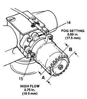
(20) Set control handle to 'FOG' position.
(21) Check housing adjustment for proper clearance (A) as shown. This adjustment determines flow rate.
(22) If adjustment is necessary loosen jam nuts (15).
Position housing (14) to obtain 0.75 in. (19.0 mm).
Tighten jam nuts firmly.
(23) Be sure control handle is set to 'FOG' position.
(24) Check sleeve adjustment for proper clearance (B)
as shown. This adjustment determines water
pattern.
(25) If adjustment is necessary loosen conduit clamp
machine screws (10). Slide cable (4) in the
direction of water flow until sleeve (13) to housing
(14) clearance is 0.69 in. (17.5 mm).
(26) Tighten machine screws (10) immediately after
adjustment.
4-265
|