|
| |
TM 5-4210-220-12
4-18. PUMP, PIPING, AND VALVES-Continued
INSTALLATION
(1)
Clean the fitting and body threads and inspect threads for
corrosion, stripped threads or cracks.
(2)
Inspect hoses and hose end fittings. Replace as required.
(3)
Clamp the body (8) in a vise. Do not overtighten. This
could damage the valve body.
(4)
Apply pipe sealant (item 22, Appendix E) to the threads
and install fittings (9) into body (8). Be sure orientation of
fittings is same as noted in REMOVAL preceding.
Remove body from vise.
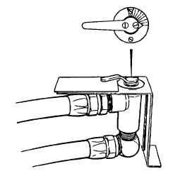
NOTE
Dial and handle can be positioned in any of the four quadrants. Be sure to position valve and
handle in the same orientation as shown.
(5)
Position metering valve beside the mounting bracket and aline the mounting holes of the body
(8), mounting bracket, and dial (7).
(6)
Install two machine screws (6) and tighten firmly.
(7)
Position the handle (4) over the extension plug (5). Install two capscrews (3) and tighten firmly. Be
sure the handle indicates the plug position in relation to the body.
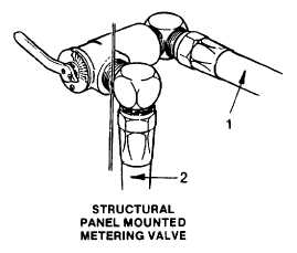
(8)
Install inlet and outlet hoses (1 and 2).
(9)
Start firefighting system as detailed in para. 2-11. Tighten/remake any leaking connections.
4-255
|