|
| |
TM 5-4210-220-12
4-18. PUMP, PIPING, AND VALVES - Continued
REMOVAL
(1)
Remove nut (1) and separate the control rod linkage (2)
control handle (8).
(2)
Set control handle (8) to the open position to eliminate
damage to the ball during removal of the valve body (5).
(3)
Remove the capscrews (3) that retain the end caps (4) to
the valve body (5). Some valve bodies are connected to
piping on one end only.
(4)
Slide valve body (5) from between end caps (4).
(5)
Remove O-rings (6) from valve body (5) grooves and
discard.
(6)
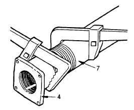
If pipe replacement is necessary, remove the end cap (4) from the pipe (7) using two pipe wrenches
(7)
Apply pipe sealant (item 22, Appendix E) to the threads of the new pipe and install the end caps (4).
Be sure to install the end cap so that it will line up with the valve body and opposite end cap.
INSTALLATION
(1)
Lubricate the O-rings (6) using silicone grease (item 27, Appendix E) and install into the valve body
(5) grooves.
(2)
Set the control handle (8) to the open position to eliminate damage to the ball during installation of
the valve body (5).
(3)
Carefully install the valve body (5) between the end caps (4). Ensure the O-rings (6) are not damage
d during installation.
(4)
Apply threadlock liquid (item 29, Appendix E) to the capscrew (3) and install the capscrews (3) through
end caps (4) into valve body (5). Tighten until snug. Do not overtighten.
(5)
Attach the control rod linkage to the control handle (8). Install the nut (1) onto ball joint and tighten firmly.
(6)
Test valve operation by actuating lever on structural control panel a few times.
4-241
|