|
| |
TM 5-4210-220-12
4-17. PUMP DRIVE AND PTO - Continued
4-17.4 Reducer Gearbox Replace - Continued
(7) Remove the three capscrews and locknuts
that are used to retain the reducer gearbox
to the mounting brackets. Discard the
locknuts.
(8) Check the mounting brackets are fastened
to the frame member.
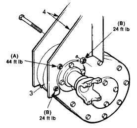
(9) Raise the reducer gearbox (3) into position
between the mounting brackets (4). Align
the holes and install the capscrews (2) and
new locknuts (1). Make sure the low speed
shaft (large gear) is facing the PTO.
(10) Tighten capscrew and locknut (A) to 44 ft lb
(60 Nm).
(11) Tighten capscrews and locknuts (B) to 24 ft lb (33 Nm).
(12) Install the fill tube and vent securely Be sure they are vertical.
(13) Fill the reducer gearbox with gear oil (item 15, Appendix E) as described in Lube Order LO 5-4210-220-12.
(14) Install reducer gear to pump drive shaft as described in para. 4-17.3.
(15) Install PTO to reducer gear drive shaft as described in para. 4-17.2.
(16) Start truck and check reducer gear operation, see Chapter 2.
4-214/(4-215 Blank)
|