|
| |
TM 5-4210-220-12
4-17. PUMP DRIVE AND PTO - Continued
(10) Install lockwashers and nuts retaining PTO
to torque converter housing. While rotating
the output shaft to and fro, tighten nuts until
either the nuts are torqued to 50 ft lb (67
Nm), or the output shaft seizes (no gear
backlash).
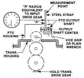
(11) Attach a steel strap to the PTO output shaft
(14) with a 'C'-clamp.
(12) Mark off 2.66 in. (67.7 cm) on the steel
strap, from the center of the output shaft
(14). This distance represents the radius of
the PTO drive gear (13).
(13) Attach dial indicator to the transmission
housing allowing combined backlash to be
measured. Measurement point is dimension
marked on steel strap.
(14) Move the output shaft in both directions. Measure the combined backlash and record as measurement 'C'.
(15) Determine the backlash (D) between the PTO side gear and the PTO drive gear using the following formula.
D = C - (A + B)
For safe PTO operation, backlash should be between 0.006 to 0.029 in. (0.15 to 0.73 mm).
(16) Adjust PTO side gear to PTO drive gear backlash by adding or deleting gaskets until correct backlash
is achieved. A 0.010 in. (0.25 mm) gasket will change backlash about 0.006 in. (0.15 mm) A 0.020 in. (0.50
mm) gasket will change backlash about 0.012 in. (0.30 mm). Do not stack more than 3 gaskets together.
Ensure that at least one gasket remains between components.
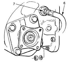
(17) Install and tighten the lubrication line (6) into the inspection plug (7).
4-205
|


