|
| |
TM 5-4210-220-12
4-15. AUXILIARY POWER UNIT - Continued
(4)
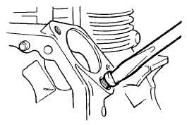
Remove fuel control lever pin. Check
diameter of pin is 0.193 - 0.197 in. (4.90 -
5.00 mm).
(5)
Check internal diameter of fuel rack and
check clearance between it and fuel
control lever pin is less than 0.006 in.
(0.15 mm) Replace/install fuel control
lever pin and fuel rack as required.
(6)
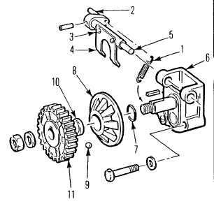
Inspect governor shaft (5) for wear
Clearance between shaft and housing
should be less than 0.006 in. (0.15 mm)
Replace components as required.
(7)
Inspect governor actuating plate (4)
Replace if tabs are worn or bent.
INSTALLATION.
(1)
Slide governor shaft (5) into housing (6)
and install governor actuating plate (4)
with screws (3).
(2)
Install six balls (9), slotted collar (10), and
moving bell (8) in governor gear (11).
(3)
Lock governor assembly to gear using
circlip (7).
(4)
Install injector pump into crankcase
ensuring pin of pump locates in the fuel
rack slot.
(5)
Install governor/oil pump assembly in
engine as detailed in para. 4-15.12, Oil
Pump Replace, steps 19 thru 24.
(6)
Tune engine as detailed in para. 4-15.14.
(7)
Install engine on base, see para. 4-15.1
ASSEMBLY.
(8)
Install APU in truck, see para. 4-15.1
INSTALLATION
4-189
|


