|
| |
TM 5-4210-220-12
4-15. AUXILIARY POWER UNIT - Continued
4-15.12 Engine Lubrication System - Continued
(5)
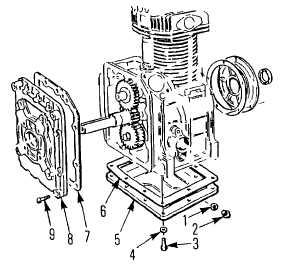
Remove crankcase cover machine screws
(9) (Oil breather tube will be removed
from engine Lay aside ).
(6)
Lift off cover (8) and gasket (7).
(7)
Remove oil pan screws (3) and washers
(4).
(8)
Lift off oil pan (5) and gasket (6).
(9)
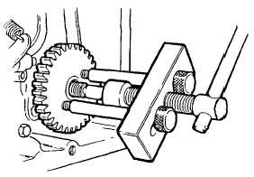
Remove oil pump/governor drive gear nut
and washer.
(10
) Using puller, remove gear from spindle
as shown Retain gear and drive key.
(11)
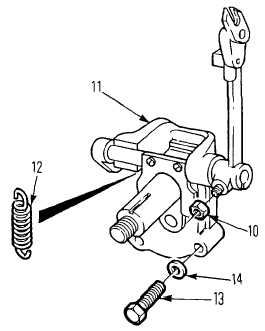
Loosen nut (10) retaining injector pump
fuel rack actuator to governor Slip shaft
off governor and remove.
(12)
Remove spring (12) from governor shaft
to pump anchor.
(13)
Remove screws (13) and washers (14)
attaching oil pump/governor assembly to
crankcase.
(14)
Lift out assembly (11) from crankcase.
(15)
Inspect oil pump by removing back plate
(Back plate may remain in crankcase. If
so remove from crankcase ).
(16)
Measure oil pump gear/housing gap. Gap
must not exceed 0.006 in. (0.15 mm)
Check side play does not exceed 0.006 in.
(0.15 mm), Replace assembly if gap or
play is excessive.
(17)
Check diameter of spindles and diameter
of spindle bushing in back plate and in
housing. Spindle to bushing clearance
must be less than 0.006 in. (0.15 mm) for
each
(of
four)
spindles.
Replace
assembly
if
any
spindle
is
out
of
tolerance.
(18)
Inspect gear teeth and side faces for
damage. Replace if required.
4-186
|


