|
| |
TM 5-4210-220-12
4-15. AUXILIARY POWER UNIT - Continued
INSPECTION
(1)
Check crankshaft and camshafts for cracks using the Magnaflux method, or similar, see para. 4-9. Replace
components if cracks are detected.
(2)
Examine shaft gears for wear, replace shaft if
teeth are cracked or pitted.
(3)
Examine crankshaft main journals and crank pin
journal for seizure marks or grooves. Light
grooves can be removed with emery cloth (Item
13, Appendix E). Replace crankshaft if marks
are severe.
(4)
Measure crankshaft journal to crankcase cover
bearing in two directions at 90 deg. to each
other. Journal must be between 1.1028 -
1.1032 in. (27.90 - 28.00 mm). Replace
crankshaft if overworn. Journal cannot be
reground.
(5)
Measure main crankshaft journals in two
directions at 90 deg. to each other.
(6)
If any journal is more than 0.004 in. (0.10 mm) out of round, or total wear exceeds 0.004 in. (0.10 mm) replace
or regrind crankshaft to next undersize.
Crankshaft Journals
Nominal 1.5756 - 1.5760 in. (39.99 - 40.00 mm)
Diameter
1st undersize 1.5658 - 1.5662 in. (39.74 - 39.75 mm)
2nd undersize 1.5559 - 1.5563 in. (39.49 - 39.50)
Crankshaft Journal
Nominal 1.5772 - 1.5780 in. (40.03 - 40.05 mm)
Bearings Diameter
1st undersize 1.5673 - 1.5681 in. (39.78 - 39.80 mm)
2nd undersize 1.5575 - 1.5586 in. (39.53 - 39.55 mm)
Bearing to journal clearance at assembly should
be 0.0012 - 0.0024 in. (0.003 - 0.006 mm),
bearings are worn out if clearance exceeds
0.007 in. (0.17 mm).
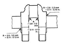
(7)
Restore journal fillet radius as illustrated. Do
not remove any material from journal flanges
facing side thrust washers.
(8)
Remove expansion plugs from crankshaft and
clean out oil ways with wire
4-177
|