|
| |
TM 5-4210-220-12
4-15. AUXILIARY POWER UNIT - Continued
4-15.8 Engine Intake and Exhaust Valves - Continued
(22)
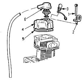
Install machine screws (1) together with
engine lift bracket(s) and tighten to 25 ft lb
(34 Nm).
(23)
Install oil breather cover (6) and ether
start plug (3).
(24)
Install left hand and right hand shrouds as
detailed in para. 4-15.9 INSTALLATION
steps 7 thru 11.
(25)
Install engine on base, see para. 4-15.1
ASSEMBLY (26) Install engine in truck,
see para. 4-15.1 INSTALLATION.
REPAIR a. Valve Guide Repair.
(1) Remove cylinder head from engine and disassemble as detailed
(2) If guides are worn they must be replaced with oversize guides.
(3) Remove valve guide retaining rings.
(4) Press guides out of cylinder head with a punch or using a suitable arbor and press.
(5) Ream guide bores. Do not use reamers more than 0.020 in. (0.5 mm) oversize.
(6) When bore is true, measure bore and machine replacement oversize guide to an outside diameter of 0.0020 -
0.0024 in. (0.05 - 0.06 mm) in excess of bore.
(7) Press in replacement guides and install retaining rings (8) Install valves in guides and ensure valve movement is
not restricted. Ream internal diameter of guides as necessary.
(9) Install cylinder head on engine as detailed in INSTALLATION preceding.
b. Valve Seat Repair.
(1) Remove cylinder head from engine and disassemble as detailed in REMOVAL preceding.
(2) If valve seats are severely worn they must be replaced.
(3) Drill three or four 0.082 - 0.12 in. (2-3 mm) holes through valve seat.
(4) Cut seat with chisel avoiding damage to seat housing.
4-166
|