|
| |
TM 5-4210-220-12
4-15. AUXILIARY POWER UNIT - Continued
(14)
Repeat test between insulated heat sink (11) and all three flat metal strips.
(15)
Disconnect black lead between regulator and rectifier bridge by removing screws (2).
(16)
Remove brush/brush holder by removing two remaining screws.
(17)
Clean brushes (12) with soft dry cloth. Replace brushes if carbon brush is less than 3/16 in. (5 mm) long.
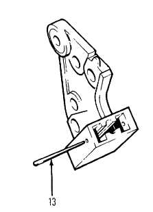
(18)
Put brushes in holder and hold with brush retainer wire (13) or toothpick as shown.
(19)
To remove rotor, hold shaft with allen key and remove nut (14), washer (15), pulley (16), fan (17) and
collar (18).
(20)
Push rotor (8) from housing.
(21)
Remove retainer plate (19) by removing screws (20).
(22)
Pushing bearing (21) out and clean all parts with a soft cloth.
(23)
Replace bearing if loose in housing or on shaft or bearing itself is worn. This is a sealed bearing, it cannot
be regreased.
(24)
When replacing press into frame with tube that presses on the outer race only.
(25)
Install retainer plate (19) using screws (20).
(26)
Push rotor (8) into end frame and assemble collar (18), fan (17), pulley (16), washer (15), and nut (14).
Tighten nut to 60 ft lb (82 Nm).
4-151
|