|
| |
TM 5-4210-220-12
1-9 LOCATION AND DESCRIPTION OF MAJOR COMPONENTS. - Continued
m.
Air System.
(1)
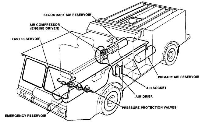
The air system comprises a main-engine-driven compressor, an air drier and four reservoirs in addition,
valves and hoses for supply and control of the truck and firefighting equipment are included, (see fig. 1-13). The
reservoirs are filled successively This is achieved with the pressure protection valves.
(2)
The primary reservoir supplies air to the rear brakes, engine throttle and firefighting system. The primary
reservoir is filled and pressurized before the other reservoirs. The air socket may be used to pressurize the primary air
system from a shop supply in the event of system overhaul.
(3)
The fast reservoir is used to store air when the engine is shut down. When the ignition is off, the reservoir
is totally isolated. When the ignition is switched on, the air starter valve opens, and the primary reservoir is pressurized.
This allows the truck to be driven without waiting for the primary tank to be charged by the compressor.
(4)
The secondary reservoir is filled after the primary reservoir is pressurized. The secondary circuit supplies
air to the front brakes, parking brake release, air horns, wipers, washers, fan, and shutter.
(5)
The emergency reservoir is filled after the primary reservoir is pressurized. The emergency reservoir only
supplies the emergency parking brake release system.
(6)
The primary, secondary, and emergency systems are fitted with pressure gages which are located in the
cab. Audiovisual alarm lamps indicate when the pressure is low. Manual draincocks are fitted to each reservoir.
Figure 1-13. Air System Components
1-14
|