|
| |
TM 5-4210-220-12
4-13 PUMP BODY - Continued
(9)
Install grease nipple(s) (11).
(10)
Install control lever bank in pump body console using four screws (4) and nuts (5). Tighten nuts to 8 ft lb (11 Nm).
(11)
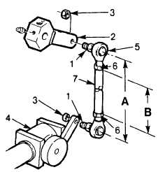
Attach tie rod linkages (1) to lever locks (2) and secure with nuts (3).
(12)
Lubricate all lever locks with white grease (item 34, Appendix E).
(13)
Install structural control panel and control rod knobs as detailed in INSTALLATION preceding.
j.
Tie Rod Linkage Repair.
NOTE
Control
panel
may
remain
installed on console.
(1)
Remove nuts (3) and pull tie rod linkage
(1) free from lever lock (2) and valve (4).
(2)
Before disassembling tie rod linkage,
measure rod end center to center distance
(A). Note this measurement.
(3) Loosen locknut (6) and unscrew tie rod end
from linkage rod.
(4)
Inspect rod (7). Minor bends may be straightened without affecting rod function. Replace rod if it is
severely damaged or either threaded end is stripped. Be sure to replace rod with one of equal length (B).
(5)
Inspect tie rod ends. Check for damage to thread, wear and corrosion. If wear or damage is
excessive, replace rod.
(6)
Install tie rod ends (5) evenly to control rod (7). If measurement (A) is available go to steps 7 and 9 if
(A) is not available go to steps 8 and 9.
(7)
Adjust position of tie rod ends to obtain dimension (A). Secure tie rod ends by tightening nuts (6)
against rod.
(8)
Adjust position of tie rod ends until linkage can be inserted into valve handle and valve lever lock. Be
sure the valve is fully closed and the lever is in the closed position. Tighten nuts (6) against rod
when correct length is obtained. Operate lever a few times ensuring valve opens and closes. Readjust
tie rods end if required.
(9)
Install linkage to lever lock (2) and valve (4) and secure with nuts (3). Tighten nuts firmly.
(10)
Lubricate all lever locks with white grease (Item 34, Appendix E).
4-127
|

