|
| |
TM 5-4210-220-12
4-12 CAB - Continued
(2) Inspect heater control valve (4). Replace valve if:
- valve shows signs of leakage.
- valve operation is sloppy, i e to much play
between stem and body.
- valve is excessively hard to open or close.
- valve cannot be fully opened or fully closed.
(3) Inspect hoses (5 and 6) Replace if leaking or signs of
swelling, cracks or brittleness are present.
(4) Use illustration as guide to replace components.
(5) Apply sealant (item 22, Appendix E) to thread of
fittings replaced.
(6) If removed, reinstall heater control cable (7) as detailed in para. 4-12.4 INSTALLATION.
(7) Install cover (3) and attach using screws (1) and nuts (3).
b. Heater Core Repair
NOTE
Heater core cannot be repaired. If leaking, replace heater unit as detailed in REMOVAL and
INSTALLATION preceding.
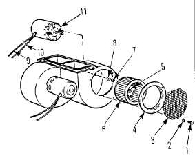
c. Blower Wheel Repair
NOTE
Blower unit may remain in truck. This instruction details repair of either blower wheel.
(1) Remove screws (1), washers (2), screen (3), and ring (4).
(2) Loosen socket head set screw (5) and pull blower wheel
(6) off motor shaft.
(3) Inspect removed parts. Damage such as minor dents or
bends in the screen, ring, or blower wheel may be
straightened. Parts with major defects must be replaced.
(4) Install blower wheel on motor shaft. Tighten screw (5)
against flat on shaft. Be sure blower wheel can spin
without interference with housing or ring (4). If
necessary, loosen screw (5) and adjust wheel position.
(5) Install ring (4) and screen (3) using washers (2) and self-
tapping screws (1).
4-107
|