|
| |
TM 5-4210-218-13&P
4-18. HALON CYLINDER ADAPTER ASSEMBLY W/GAUGE. REPAIR. (Refer to Figure 4-10)
This task covers:
a.
Removal
b.
Installation
INITIAL SETUP
Equipment Condition
Tools
Reference
General Mechanics Tool Box, Item 1, Section
Cover removed from Recovery / Recharger
III, Appendix B.
paragraph 2-6.1
Materials/Parts
Air supply disconnected, paragraph 2-7
Self-locking nuts
Hose
4-20.1 Removal.
NOTE
Make certain that all Halon has been recovered from the hose before breaking any
connection.
a.
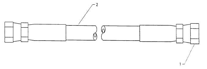
Disconnect the hose swivel couplings (1) at each end of hose.
b.
Remove hose (2).
4-20.2 Installation.
a.
Remove any remaining antiseize tape from the hose connection points.
b.
Wrap male connecting threads with one layer of antiseize tape (item 3, Section II, Appendix F)
c.
Connect hose swivel couplings (1) to correct connection points and tighten.
Figure 4-13. Hose Replacement
4-29
|

