|
| |
1
Heater, vehicular compartment
2
Connector
3
Lead, electrical
4
Panel top
5
Grommet
6
Screw
7
Nut, stamped
8
Cover assembly, front
9
Motor and wheel assembly,
adapter
10
Screw, cap, hex head
11
Motor, D.C.
12
Nut, stamped
13
Gasket, motor mounting
14
Lead electrical
15
Suppressor
16
Wheel, blower
17
Housing, blower
18
Screw, tapping, thread cutting
19
Washer, lock
20
Defroster Y
21
Screw
22
Washer, lock
23
Gasket, blower housing
24
Spacer
25
Motor and fan assembly, heater
26
Screw assembly
27
Bracket, motor mounting
28
Washer, flat
29
Nut assembly, washer
30
Motor, D.C.
31
Setscrew
32
Fan
33
Screw assembly, washer
34
Nut assembly, washer
35
Screw assembly, washer
36
Lead, electrical
37
Housing, heater
38
Block, shutter
39
Spacer, core ends top and
bottom
40
Spacer, core ends
41
Core, heater
42
Switch, toggle
Figure 3-51--Continued.
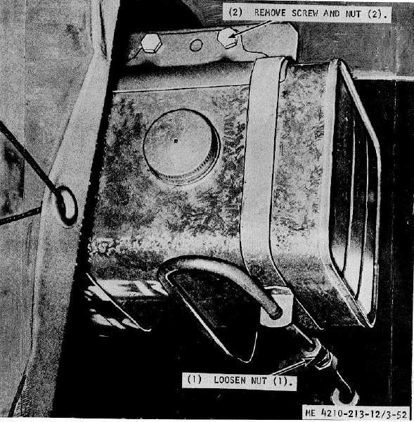
Figure 3-52. Oil tank and lines, removal and installation.
3-67
|