|
| |
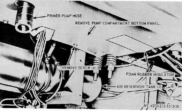
Figure 3-39. Pump compartment panel, removal and installation.
Section XlIl. PUMPING SYSTEM
3-86. General
The fire truck pumping system consists of a centrifugal
type pump rotary vacuum priming pump, steady valve,
relief valve; water tank, foam and two motor driven hose
reels. A series of operating valves, drain valve, and a
foam metering valve. Regulate operation of the fire
pump for pumping water, or a water and foam
combination. The centrifugal type pump develops
pressure and capacity, by means of centrifugal force,
and must be primed before it will lift water. The priming
system consists of a rotary vacuum pump operated by a
24-volt electric motor controlled through a manual
priming valve which activates a microswitch controlling
the electric motor. Water pressure is controlled
manually by a throttle knob and is held automatically by
a relief valve. The relief valve is adjusted to any pump
pressure up to 300 psi. The hose reels are electric
motor driven, and actuated by a reel rewind button,
located beneath the hose reel assemblies on the
instrument panel. The heat exchanger is mounted in the
engine
compartment, and circulates water through the engine
cooling system from the pumping system to cool the
engine. The primer oil tank is mounted on the engine
cab beneath the right hand seat. It supplies oil to the
primer pump.
3-87. Primer Pump
a.
Removal.
(1)
Remove the primer pump motor and
solenoid relay (para 3-71).
(2)
Refer to figure 3-40, and remove and
replace defective primer pump from the fire pump
manifold.
b.
Installation. Install the primer pump motor and
solenoid relay (para 3-71).
3-88. Hose Reel
a.
Removal.
(1)
Remove the hose reel motor solenoid
(para 3-68).
(2)
Remove the hose reel motor (para 3-69) -
(3)
Refer to figure 3-41, and remove the
3-55
|