|
| |
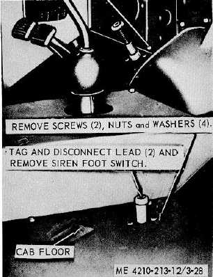
Figure 3-28. Siren foot switch, removal and
installation.
3-72. Microswitch
Refer to figure 3-32, and remove and replace defective
microswitch from the primer valve.
3-73. Rear Spot light
a.
Removal. Refer to figure 3-33, and remove the
rear ILO spotlight from the ladder support.
b.
Cleaning, Inspection, and Repair.
(1)
Clean all parts with a clean cloth
dampened in an approved cleaning solvent, and dry
thoroughly.
(2)
Inspect all parts for damaged or defective
condition.
(3)
Replace or repair damaged or defective
parts as necessary.
c.
Installation. Refer to figure 3-33, and install the
rear ILO spotlight on the fire truck body.
3-74. Tail lights
a.
Removal. Refer to figure 3-34, and remove the
tail lights from the fire truck panel.
b.
Cleaning, inspection, and Repair.
(1)
Clean all parts with a clean cloth
dampened in an approved cleaning solvent, and dry
thoroughly.
(2)
Inspect all parts for damaged or defective
condition.
(3)
Replace or repair damaged or defective
parts as necessary.
c.
Installation. Refer to figure 3-34, and install the
tail lights on the fire truck panel.
3-75. Battery Charging Receptacles
a.
Removal. Refer to figure 3-34, and remove the
battery charging receptacles from the rear apron.
b.
Cleaning, Inspection, and Repair.
(1)
Clean all parts with a clean cloth
dampened in an approved cleaning solvent, and dry
thoroughly.
(2)
Inspect all parts for damaged or defective
condition.
(3)
Replace or repair damaged or defective
parts as necessary.
c.
Installation. Refer to figure 3-34, and install the
battery charging receptacles on the rear apron.
3-76. Battery and Battery Cables
a.
Removal. Refer to figure 3-14A and remove
and replace defective cables and batteries.
3-40
|