|
| |
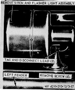
Figure 3-17. Siren and flasher light, removal and
installation.
remove the pump gage panel warning light from the
pump gage panel.
b.
Cleaning, Inspection, and Repair.
(1)
Clean all parts with a clean cloth
dampened in an approved cleaning solvent, and dry
thoroughly.
(2)
Inspect all parts for damaged or defective
condition.
(3)
Replace or repair damaged or defective
parts as necessary.
c.
Installation. Refer to figure 3-29, and install the
pump gage panel warning light on the pump gage panel.
3-62. Pump Gage Panel Light
a.
Removal. Refer to figure 3-29, and remove the
pump gage panel light from the; pump gage panel.
b.
Cleaning Inspection and Repair.
(1)
Clean all parts with a clean cloth
dampened in an approved cleaning solvent, and dry
thoroughly.
(2)
Inspect all parts for damaged or defective
condition.
(3)
Replace or repair damaged or defective
parts as necessary.
c. Installation. Refer to figure 3-29, and in-
stall pump panel lights on the pump gage panel.
3-3. Dome light
a.
Removal. Refer to figure 3-0, and remove the
dome light from the special purpose body.
b.
Inspection, and Repair.
(1)
Inspect all parts for damaged or defective
condition.
(2)
Replace or repair damaged or defective
parts as necessary.
c.
Installation. Refer to figure 3 30, and install the
dome light on the special purpose body.
3-64. Dome light Switch
Refer to figure 3-30, and remove and replace defective
dome light switch from the instrument panel.
3-65. Pump Gage Panel Light Switch
Refer to figure 3-0, and remove and replace defective
pump gage panel light switch from the instrument panel.
3-66. Engine Light Switch
Refer to figure 3-30, and remove and replace defective-
engine light switch from the instrument panel.
3-67. Hose Reel Switch
Refer ' to figure 3-0, and remove and replace defective
hose reel switch from the instrument panel.
3-68. Hose Reel Motor Solenoid Relay Refer to figure
3-1, and remove and replace defective 'hose reel motor
solenoid relay from the hose' reel.
3-69. Hose Reel Motor Refer to figure 3-31' and
remove and replace defective hose reel motor from
hose reel.
3-70. Primer Pump Motor Solenoid Relay Refer to
figure 3-2, and remove and replace defective primer
pump motor solenoid relay from the primer pump.
3-71. Primer Pump Motor Refer to figure 3-32, and
remove and replace defective primer pump motor from
the primer pump.
3-29
|