Order this information in Print

Order this information on CD-ROM

Download in PDF Format


Click here to make tpub.com your Home Page

Page Title: Figure 4-3. Cylinder Valves
Back | Up | Next

Click here for a printable version

Google


Web
www.tpub.com

Home


Information Categories
.... Administration
Advancement
Aerographer
Automotive
Aviation
Combat
Construction
Diving
Draftsman
Engineering
Electronics
Food and Cooking
Math
Medical
Music
Nuclear Fundamentals
Photography
Religion
USMC
   
Products
  Educational CD-ROM's
Printed Manuals
Downloadable Books


TM 10-4210-235-13 NOTE 
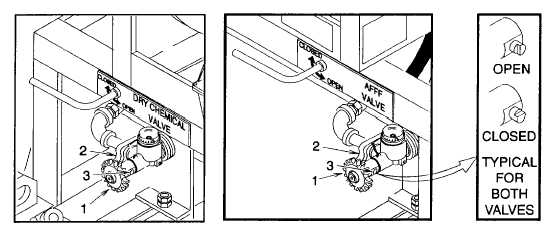
Procedures are the same for either the dry chemical or AFFF system. (1) Close cylinder valve if open (a) Turn cylinder valve hand wheel (1) (fig.  4-3) fully counterclockwise (open). (b) Close (lower) quick release lever (2) and rotate cross shaft (3) until flat is horizontal (c) Turn hand wheel (1) fully clockwise (closed).                    Figure 4-3.  Cylinder Valves (2) Relieve system pressure  (a) Remove strip tie (1) (fig.  4-4). (b) Pull retaining clip (2). (c) Open ball valve (3). (d) Squeeze fire hose nozzle valve lever (1) (fig 4-5) to relieve system pressure. (e) Close ball valve (3) (fig 4-4) (f) Install retaining clip (2) over ball valve (3) handle. (g) Install new strip tie (1). 4-15

Privacy Statement - Press Release - Copyright Information. - Contact Us - Support Integrated Publishing

Integrated Publishing, Inc. - A (SDVOSB) Service Disabled Veteran Owned Small Business